


Pulse Induction Metal Detector M158.2v1 Modul
Original price was: 23,80 €.16,66 €Current price is: 16,66 €. Incl. VAT, excl. shipping – calculated at checkout
Pulse metal detector – the module is designed for the manufacture of a metal detector that allows to detect objects from ferrous and non-ferrous metals
9 in stock
- Satisfaction Guaranteed
- No Hassle Refunds
- Secure Payments
Description
Specifications
➔ Depth of detection of a coin, cm 20 – 25 cm
➔ The depth of detection of the coin, 100 – 150 cm
➔ Power supply, 9-14 B
➔ Current consumption 60 – 70 mA
➔ Pulsed current consumption, 1 – 2 A
➔ Overall dimensions of the board, 45 X 43 mm
*The current consumption depends on the volume setting of the
speaker. At maximum volume, it can reach up to 240mA.
Assembly and configuration of the metal detector
The device consists of two main nodes: transmitting and receiving. The transmitting node consists of a pulse generator on the chip U1 (NE555) and a powerful key on the transistor Q2. The receiving node is assembled on the chip U2, diodes D1, D2, on R8 and transistor Q3. The excitation signal from pin 3 of U1 is transmitted periodically to the coil of the sensor, through Q1, Q2 in the form of pulses with a duration of 125-150 μs and a frequency of 125-150 Hz. In conducting objects, damped eddy currents are induced, which excite a damped electromagnetic field. Depending on the conductive properties and size of the object, the signal changes its shape and duration, standing out on the detector D1, D2, R8. Further, the signal, amplified by U2A, goes to the scheme of the selection of the useful signal collected on RV1, RV2, C6, R12, R13, C7, U2B. Adjusting the resistances of RV1, RV2, and is achieved by setting the maximum sensitivity of the device, a state in which the signal no longer passes through the threshold in the output speaker. And if you now bring the metal to the coil, the signal, having slightly increased, overcomes the trigger threshold and enters the speaker, signaling that “there is a find.”
Assembling and setting up a metal detector
Settings are carried out away from industrial interference and large metal objects. If at this moment any metal object is near the sensor coil, the device, it is wrong. The power voltage is supplied to the contacts +VCC, 12V from the battery (in cases with the power supply, there may be interference that will lead to difficulty setting up the device). The search coil is connected to the contact L1, and the SP1 contact is 8 Ohms/0.5 watts. When feeding, the device is initiated by the device accompanied by blinking and characteristic sound. The
SW3 SW6 buttons set the minimum barrier value. The tuning resistor R3 is rotated until the device begins to make sounds on its own, and then we turn the R3 a little so that the device is silent. At each position of the tuning resistor, we press the SW4 reset button and check the sensitivity. A good result by air can be considered 22-25 cm for five cents. The setting of the metal detector can be considered finished. To look for a metal, we install a barrier in which the “instinct” of the device will be maximum with satisfactory stability. A well-tuned device does not give false works at 3-4 barrier LEDs.
Making a search coil
For the manufacture of the search coil, you need a rigid non-metallic mandrel Ø 200-250 mm, copper winding enamelled sew wire (Ø0.4 – 0.6 mm) 20 meters long, copper insulated stranded wire 2×1.5 mm2, 120-150 cm long fee. On the mandrel tightly wind 25 turns of magnet wire. Attach the ends of the wire and solder them using soldering insulated wire with the board to the L1 contacts.
Assembly the setting of the metal detector
Connect the speaker 8 ohm 0.5 W to the Speaker1 contacts. Connect the coil to contacts L1. Connect power to the contacts of Power1 9-14 Volts, while respecting the polarity! Preferably from the battery 12 V, 1.2 Ah.
Check the connection and fastening of the board again !!! Before switching on, make sure that there are no metal and electrical components and devices in the coil area: such as a mobile phone, a system unit, reinforcement rods in concrete or walls or floors, and metal profiles in the walls, or the presence of metal inside the desktop, and in the area where the device is configured, etc.
After turning on the device, bring the variable resistor RV1 (fine tuning) engine to the middle position. Rotate the trimmer resistor RV2 (coarse tuning) to find the position at which the clicks in the dynamics will begin or disappear. Leave in the position of still audible clicks. Slightly unscrew the resistor RV1 so that the clicks in the speaker subside. So leave. Maximum sensitivity is achieved at the threshold of sound in the speaker. Sensitivity can be increased by increasing the number of turns of the coil. With a mandrel diameter of 250 mm and a wire diameter of 0.5 mm, the number of turns is 25. This quantity is optimal in terms of power consumption (battery life) and detection depth.
After setting the maximum sensitivity, bring the metal object to the coil and observe the appearance of a stable signal in the dynamics and its extinction as you move away from the coil. The device is ready for operation. In the process, you can always adjust the sensitivity of the variable resistor RV1 (or even RV2 (roughly)).
Pleasant searches and finds
Quick User Guide ![]()
Additional information
| Weight | 0,3 kg |
|---|
Related products
-
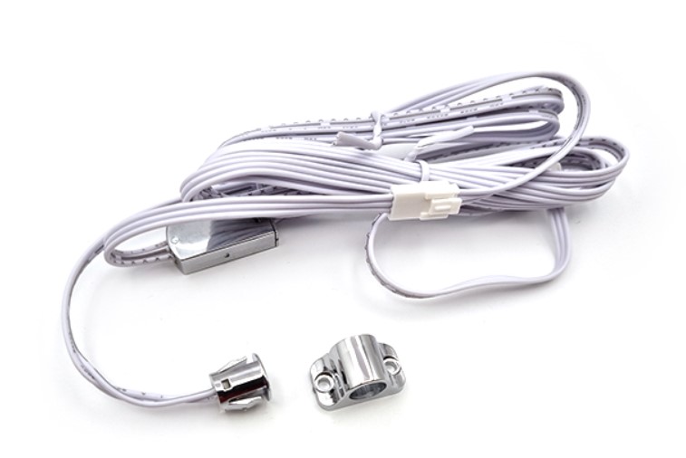
Optical sensor cylindrical furniture CTR-0578 ON/OFF for door opening
11,31 € Incl. VAT, excl. shipping – calculated at checkout -
Sale!
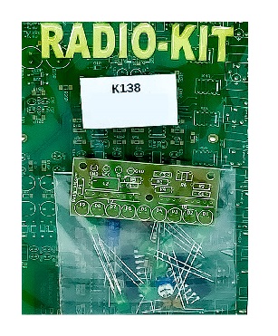
LED VU meter audio level indicator K138 KIT
Original price was: 17,85 €.9,52 €Current price is: 9,52 €. Incl. VAT, excl. shipping – calculated at checkout -
Sale!
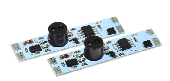
Optical sensor for profile I=3A, straight with dimming M314D-3A (4 brightness levels)
Original price was: 11,90 €.7,14 €Current price is: 7,14 €. Incl. VAT, excl. shipping – calculated at checkout -
Sale!
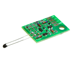
Electronic fan temperature controller 12-24V DC 0,7A M261.1 Modul
Original price was: 4,76 €.3,57 €Current price is: 3,57 €. Incl. VAT, excl. shipping – calculated at checkout
Reviews
There are no reviews yet.