
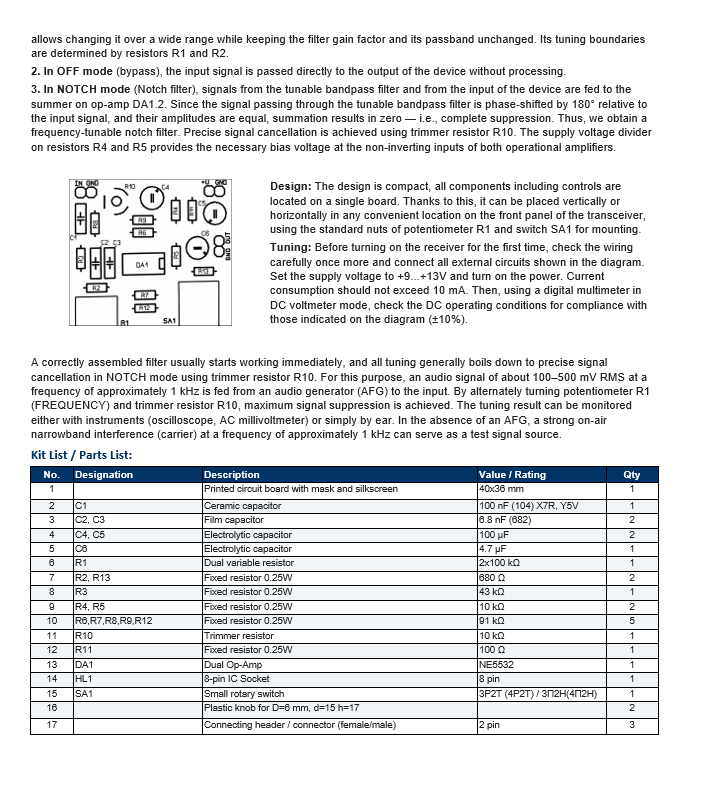
CW / NOTCH Audio Filter for HF Transceivers – DIY Kit
Original price was: 30,00 €.24,00 €Current price is: 24,00 €.
Build your own CW / NOTCH audio filter for HF ham radio. Adjustable 450–3100 Hz, 500 Hz bandwidth, up to 40 dB rejection. Complete DIY kit.
2 in stock
- Satisfaction Guaranteed
- No Hassle Refunds
- Secure Payments
Description
CW / NOTCH Audio Filter for HF Transceivers – DIY Kit
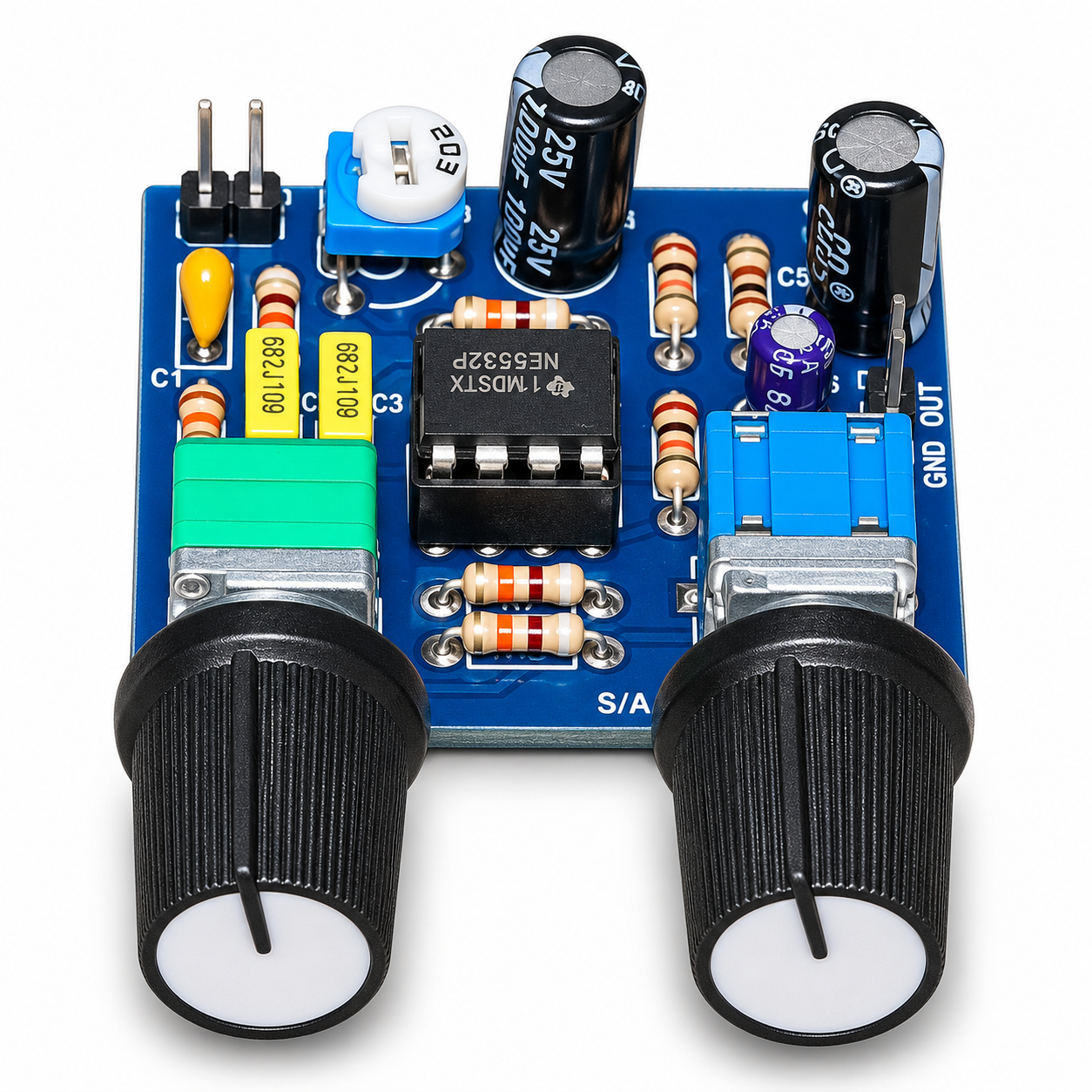
The CW / NOTCH Audio Filter is a compact, adjustable active audio filter designed for amateur HF transceivers and receivers operating in CW and SSB modes.
It helps isolate weak CW signals, reduce interference from adjacent stations, and suppress unwanted tones or carrier signals.
The filter operates in the low-level audio signal path and provides adjustable frequency control for selecting the desired signal or rejecting interference.
Key Features & Operating Modes:
- CW Mode: Tunable narrowband filter that isolates the desired telegraph signal while attenuating signals outside the selected frequency range.
- NOTCH Mode: Adjustable rejection filter for suppressing unwanted tones and carrier signals. Internal trimmer R10 allows precise adjustment of the rejection depth.
- OFF Mode: Bypass function that passes the input audio signal directly to the output without filtering.
- Frequency Adjustment: The FREQUENCY potentiometer allows continuous tuning across the operating range.
- Compact Design: All components and controls are mounted on a single PCB, suitable for installation inside a transceiver or receiver.
Technical Specifications:
- Frequency Range: 450–3100 Hz
- Filter Bandwidth: 500 Hz
- Rejection Depth: Up to 40 dB
- Input Signal Level: 100–500 mV RMS
- Voltage Gain: 1 (Unity Gain)
- Power Supply: DC +9V to +13V
- Current Consumption: Less than 10 mA
- Maximum Source Impedance: 5 kΩ
- Minimum Load Impedance: 5 kΩ
- PCB Dimensions: 40 × 36 mm
- Operational Amplifier: NE5532
Important Connection Information:
The filter is designed for low-level audio signals, such as those available from a suitable line-level output or internal audio circuit of a transceiver or receiver.
Do not connect the filter directly between an amplified speaker output and a loudspeaker.
Circuit Description:
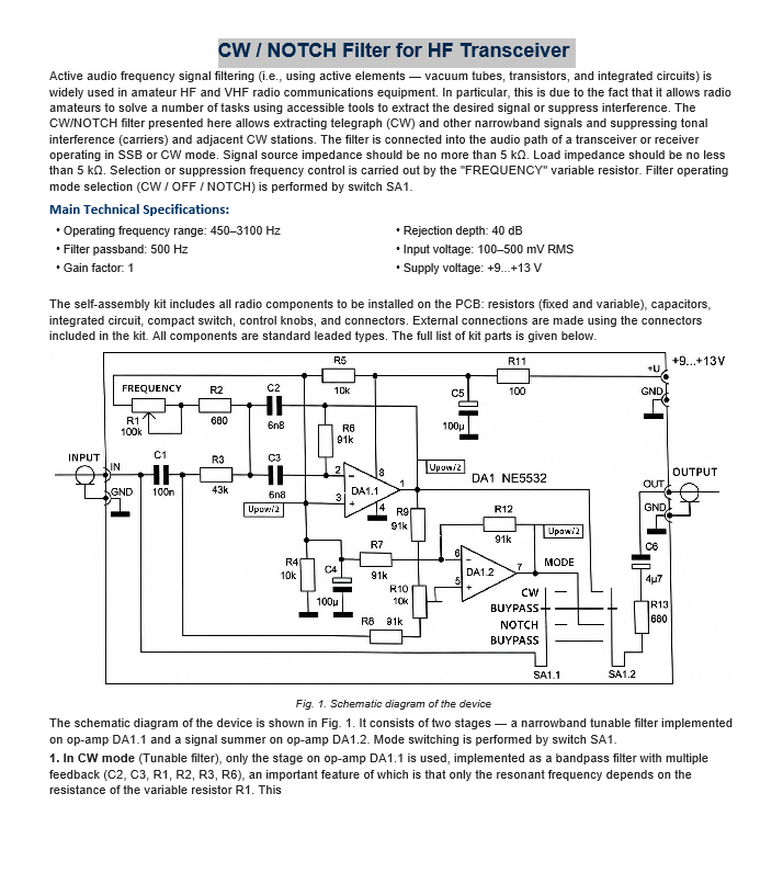
The circuit is based on a dual NE5532 operational amplifier and consists of two stages.
- DA1.1 – Tunable Bandpass Filter: A multiple-feedback bandpass filter using C2, C3, R1, R2, R3, and R6. The dual potentiometer R1 adjusts the resonant frequency while maintaining the filter bandwidth and gain.
- DA1.2 – Summing Stage: Combines the original audio signal with the phase-shifted filtered signal to cancel the selected frequency component in NOTCH mode.
- SA1: Selects CW, OFF, or NOTCH operation.
- R10: Trimmer for precise NOTCH rejection adjustment.
Assembly & Adjustment:
Before applying power, check all components, solder joints, and external connections against the schematic diagram.
Apply DC +9V to +13V and verify the operating voltages with a digital multimeter. Current consumption should remain below 10 mA.
For NOTCH adjustment, apply an audio signal of approximately 1 kHz at 100–500 mV RMS. Adjust the FREQUENCY potentiometer R1 and trimmer R10 alternately until maximum signal suppression is achieved.
The result can be checked using an oscilloscope, AC millivoltmeter, or by listening.
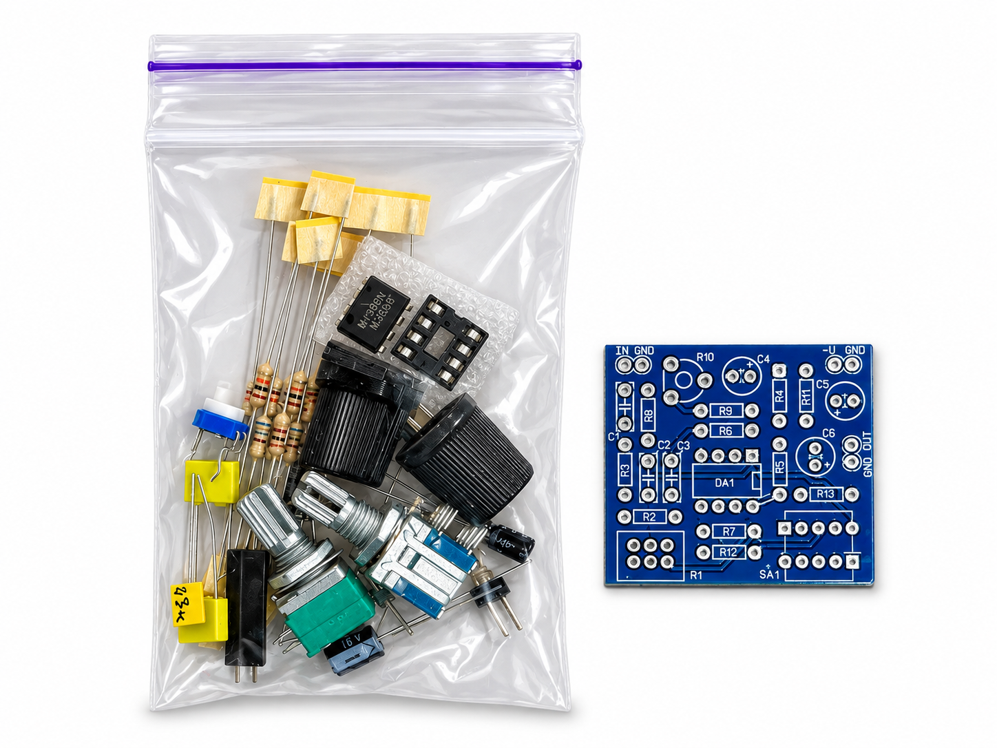
DIY Kit Contents:
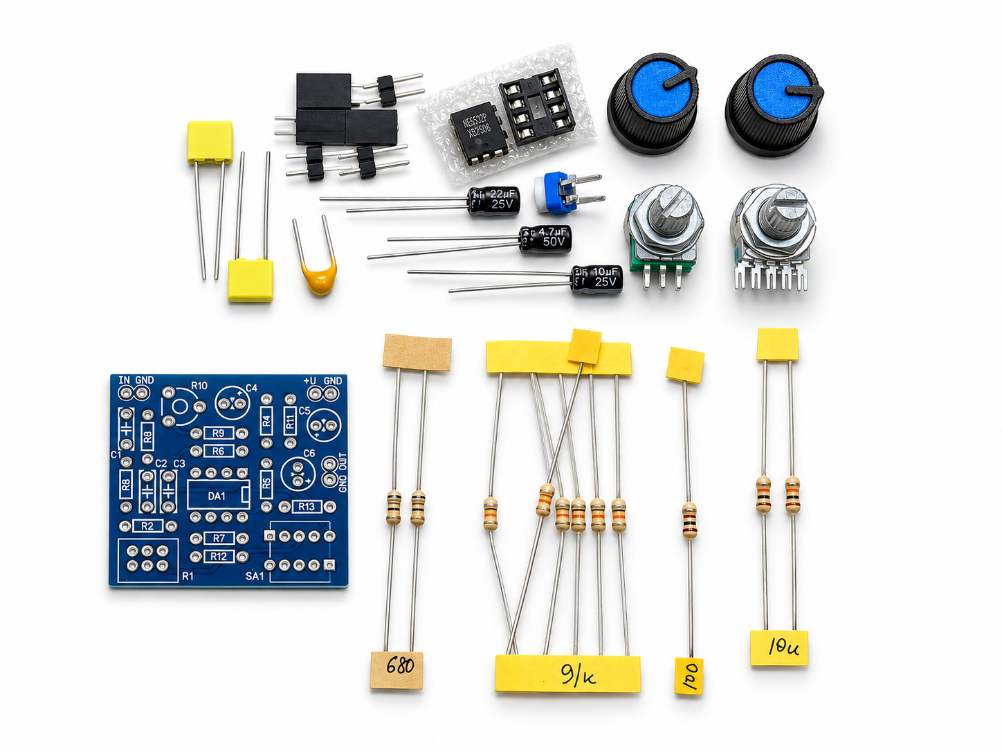
- Printed circuit board with solder mask and silkscreen.
- NE5532 dual operational amplifier and 8-pin IC socket.
- All required resistors and capacitors.
- Dual 100 kΩ frequency control potentiometer.
- 10 kΩ adjustment trimmer.
- Rotary mode selector switch.
- Two control knobs.
- Connection headers and connectors.
Please Note: This product is supplied as a DIY assembly kit, not as a fully assembled device. Soldering, installation, and adjustment are required.
Additional information
| Weight | 0,3 kg |
|---|---|
| Dimensions | 17 × 17 × 3 cm |
| LCD 1.8'', 5-12VDC, I=60mA | Digital S-meter for any radio. Connected to the audio or RF output. |
Related products
-
Sale!
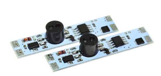
Optical sensor for profile I=3A, straight with dimming M314D-3A (4 brightness levels)
Original price was: 10,00 €.6,00 €Current price is: 6,00 €. -
Sale!
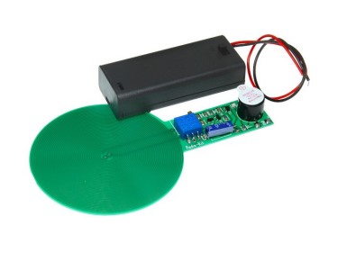
Hand Metal Detector M158.3 Modul
Original price was: 12,00 €.6,00 €Current price is: 6,00 €. -
Sale!

Headphone amplifier on NE5532 K275 KIT
Original price was: 10,00 €.6,00 €Current price is: 6,00 €. -
Sale!

Laboratory Power Supply K178 Kit
Original price was: 15,00 €.12,00 €Current price is: 12,00 €.
Reviews
There are no reviews yet.